How to Build the Weilandfilm Theatrical Poster Lightbox
Lighting
DISCLAIMER:
I AM NOT A LICENSED ELECTRICIAN NOR DO I CLAIM TO BE ONE. The electrical solutions I depict here have worked successfully for me. However, I can not vouch for their reliability with regard to national or local electrical codes. By using the information and instructions on this page, you acknowledge that you do so via your own free will and willingly relinquish me (Ed Weiland) from any liability associated with the construction and/or electrical wiring of the lightbox depicted here. Use of these instructions may void your homeowner’s insurance.
Let There Be Light…
After the hull is painted (inside and outside) we’re ready to install the
ballast, lampholders, switch and fuse as well as wire everything together.
Materials needed for this section:
| (1) | Electronic Ballast (suggested Magnetek 120V 60Hz) |
| (3) | T-8, 36-inch, 30 watt warm white fluorescent lamps |
| (6) | Fluorescent lampholders (suggested Leviton #13181-U roughly 1-9/16″ in height. See also Advance Transformer #FR-BP at advancetransformer.com) |
| (1) | Fuse holder with fuse (300V /1.5A) |
| (1) | Power toggle switch (suggested: Gardner Bender Toggle #GSW-125; 6 amp 125 VAC/CA; 3 amp 250 VAC/CA; single pole – single throw) |
| (1) | 10-feet of #16 AWG wire (#14 AWG will work — but is a bit too large) NOTE: Depending on how much leader wire your ballast has, you may require much less than 15-feet. However, this wire is very inexpensive.) |
First, mount and screw the ballast to the bottom inside of the hull being sure to center it left to right. For clearance purposes, be sure to mount the ballast tight against the hull’s backing so that there will be enough room for the inner Plexiglas to clear at the front of the lightbox. This is where that critical ballast dimension of 2-7/16″ or less comes into play.
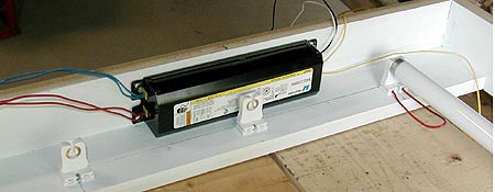
Figure 5.1: Ballast and Lower Lampholder Assembly
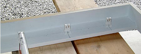
Figure 5.2: Upper Lampholder Assembly
Next, attach the upper three lampholders to the top back brace. The upper three lampholders are horizontally spaced the same as the lower holders. You can use a lamp to correctly space each of the upper lampholders the right distance from the lower lampholders and consequently screw each of them into the top back brace.
Please note that depending on the type of lampholder you purchase, you may have to further secure each lampholder so it doesn’t spin or move when a bulb is inserted. In each of the two lightboxes I’ve constructed, I’ve had to place a small piece of trim behind each set of three holders to keep them from sliding off their screw mount. See Figure 5.7.
Wiring the Lampholders to the Ballast
Once the lampholders are secured, we’re ready to start wiring. Please consult the wiring diagram (Figure 5.3) below. If you’re familiar with wiring a ballast to lampholders, you can wire this on your own and come back to the switch-mouting section below.
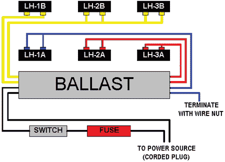
Figure 5.3: Lightbox Wiring Detail (for four-lamp ballast)
In the above diagram, the three pair (LH-1A & LH-1B, LH-2A & LH-2B and LH-3A & LH-3B) of lampholders that have been installed are shown. The ballast I used, can accommodate three or four lamps, so it has two blue and two red wires at one end of the ballast. At the other end are two yellow wires, a black wire and a white wire. For reference, see Figures 5.4 and 5.5 for wiring details that are typically found on ballast casings.
When wiring a lampholder, each of its two terminals must be connected to the same ballast wire. In the case of the lower lampholders, each is connected to a dedicated blue or red wire (or just blue depending on the type of ballast used.) Look closely at each lampholder. It has four wire inlets — two for each terminal. In the case of a four-lamp ballast, simply insert a red wire from the ballast into one of the lampholder’s inlets for the left terminal. Once secure, then insert a small piece of jumper wire (4 inches or so) into the left terminal’s other inlet and connect the terminals by inserting the jumper’s other end into an inlet on the right terminal. See Figure 5.6. Also see the red jumper used on the lampholder to the right of the ballast in Figure 5.1. Wire each of the three lower lampholders, and if you have a four-lamp ballast, simply terminate the remaining blue wire with a wire nut. If you have a three-lamp ballast, consult Figure 5.5.
Similarly, wire the upper lampholders to the ballast with the two yellow wires. Note that one lampholder will have a dedicated yellow wire, while the other two lampholders will share the other yellow wire. See Figure 5.7.
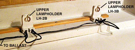
Figure 5.7: Upper Lampholder Wiring
Upper lampholders LH-2B and LH-3B. Please note that since the yellow wires from the ballast were not long enough to feed the upper lampholders, I used black wire (instead of yellow) to extend the yellow leads to the upper lampholders.
After connecting LH-1B to it’s own yellow ballast wire, the other yellow wire feeds the bottom inlet of LH-2B’s left terminal. A jumper connects LH-2B’s top inlets. A jumper is then employed from the bottom inlet of LH-2B’s right terminal and then feeds the bottom inlet of LH-3B’s left terminal. Finally, a jumper connects LH-3B’s left and right terminals across the top inlets.
Using wire nuts/connectors, wire the switch and fuse in series. Drill a hole out the back side of the lightbox where you want the power cord to exit and connect it to the fuse. I simply used a three-prong (with ground) white extension cord. Finally, I connected the extension cords grounding wire to the ballast’s casing to ground it.
Mounting the Switch
Once everything is wired, you will need to mount the switch. You may have to fuss with mounting the particular switch you select (I used a Gardner Bender Toggle #GSW-125) — but I simply marked the location of my switch on the inside of the box. Using a 1-inch drill bit, I bored a hole roughly 3/8″ into the bottom of the lightbox. Then I used a ½” bit to drill an off-center hole for the switch’s toggle portion to stick through. See Figure 5.8 to see the desired outcome. To be sure that enough length of switch protruded through, I returned to the 1-inch bit, bored deeper into the bottom panel and installed my switch.
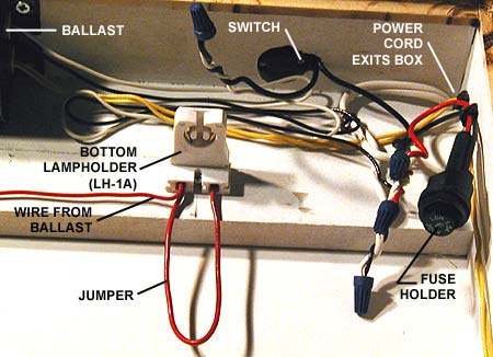
Figure 5.10: Switch and Fuse Holder Wiring Layout
With the ballast, lamps, fuse and switch wired, you can now secure all of your wiring with insulated wire staples. You won’t need many, since most of the wire is rather rigid and should stay put quite well. Now we’re now ready to move on to the front framework of aluminum angles that will hold the Plexiglas in place.
Reference Diagrams
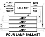
Figure 5.4: Wiring detail for a four-lamp ballast. NOTE: Cap one of the blue leads if using only three lamps like proposed in this outline.
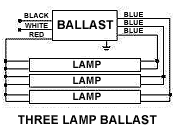
Figure 5.5: Wiring detail for a three-lamp ballast.
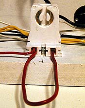
Figure 5.6: Lampholder wiring connection and jumper. A red lead from the ballast is inserted into the top part of the left terminal. A jumper wire then connects the bottom part of the left terminal to the right terminal.
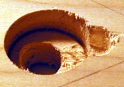
Figure 5.8: Sample boring for switch on the inside of the lightbox hull.
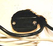
Figure 5.9: Switch inserted into the hole bored on the inside of the lightbox hull.