How to Build the Weilandfilm Theatrical Poster Lightbox
The Hull
A Good Foundation
The lightbox framework is comprised of 1×4 poplar boards. I chose poplar because it’s lightweight and easy to work with. And unlike pine, it shouldn’t warp or twist after being subjected to the contained heat of the lamps inside that will illuminate the box.
The hull consists of six pieces of 1×4 poplar (3/4″ x 3-1/2″ actual cross-section dimensions) of the following lengths:
- (2) side panel pieces measuring 41-1/4″
- (2) top/bottom panel pieces measuring 26-3/4″
- (2) back brace pieces measuring 28-1/4″
If you’re trying to keep the cost of materials down and minimize waste, you can achieve these lengths of poplar by purchasing one 1×4 @ 7-foot and one 1×4 @ 10-foot. Cut the two 41-1/4″ pieces from the 7-footer; Cut the four other pieces from the 10-footer.
After cutting the necessary lengths of poplar, create two notches in each of the 41-1/4″ pieces. See Figure 4.1. Each 3/4″ x 3-1/2″ notch needs to be cut 3/4″ in from each end. Later on, these notches will accept the two back braces used to stabilize the frame.
Before attaching any panels together, assemble the side panels (41-1/4″) and top/bottom panels (26-3/4″) as shown in Figure 4.2 making sure that the top and bottom panels are inside the side panels, creating a framework measuring 41-1/4″ x 28-1/4″ overall (outside dimensions.)
 Next, pre-drill two pilot holes at each end of each side panel. Each set of two holes should be 3/8″ in from the edge and spaced 2-3/4″ apart from each other. See Figure 4.1. Since 1-5/8″ drywall screws will be used, a 1/16-inch drill bit should create an adequate pilot hole. After pre-drilling, use a larger bit and drill enough of the pilot hole out so that when the screws are driven in, the screw heads can be countersunk. If you do not drill pilot holes, the poplar will likely split. Once all the pilot holes have been drilled, use wood glue at each corner and screw everything together.
Now fit each of the 28-1/4″ back brace pieces into each set of notches of the framework. See Fig’s 4.4 and 4.5. Drill pilot holes and apply wood glue as before and screw everything together with drywall screws.
After the framework is complete, attach a 1/8″ masonite back panel with trim nails to the back of the lightbox. Make sure that the panel is cut slightly smaller than the lightbox itself so that the masonite won’t protrude out past the edges of the frame and impact the ornate trim that will be attached later.
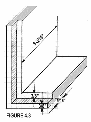
Next, the front inside edge of the hull needs to be routed with a 3/8″ rabbeting router bit set at depth of 5/16″. The inner Plexiglas panel will rest in this recess. Once routed, you will need to chisel out the rounded corners left by the router. See Figure 4.3.
Please note: before routing anything, make sure that your ballast depth is 2-7/16″ or less. If not, you will have to decrease the router depth so the ballast will fit in the space between the lower back brace and the inside Plexiglas.
Next, to increase lamp reflectivity, paint the entire inside of the of the hull white with spray paint. Apply several light coats of paint since the masonite will warp if too much paint is applied too quickly. You may need two cans of spray paint for adequate coverage.
Lastly, mask off the entire face of the lightbox frame with newspaper and masking tape and paint the outside of the box whatever color you desire. I suggest using Rust-Oleum’s American Accents Satin spray paints.
I’ve used both #7943 Midnight Blue and #7945 Claret Wine. You may want to prime the surface first too. The poplar tends to suck up quite a bit of paint which forces you to apply numerous coats — especially if you select a dark color.
After having built and painted the hull, we can now install the ballast, lampholders and wiring.
But first, here are the working drawings (Figures 4.8, 4.9 and 4.10 below) for your reference.
Reference Diagrams
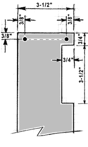
Fig. 4.1: Notch in side panel for back brace
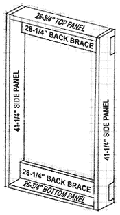
Fig. 4.2: Hull assembly
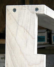
Fig. 4.4: Notch for back brace
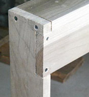
Fig. 4.5: Back brace assembly
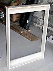
Fig. 4.6: Framework front
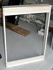
Fig. 4.7: Framework rear
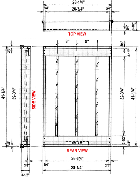
Figure 4.8: Lightbox Working Drawings (Rear – Side – Top Views)
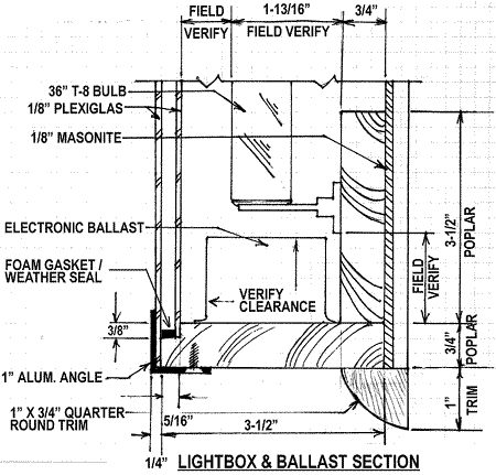
Figure 4.9: Section Through Ballast at Lightbox Bottom)
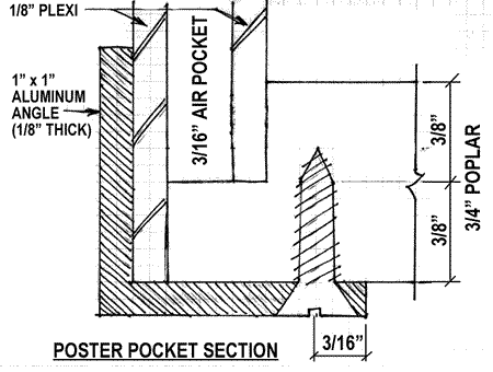
Figure 4.10: Section: Aluminum Angle, Plexiglas and Air Pocket